|
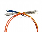
Figure 1 Mode-Conditioning Patch Cord When using 1000BASE-LX/LH, 10GBASE-LX4 and 10GBASE-LRM transceivers with legacy 62.5-micron or 50-micron MMF, you must install a mode-conditioning patch cord between the transceiver and the MMF cable on both ends of the link. The patch cord is required as per IEEE standard and Cisco specification for all links over FDDI-grade, OM1 and OM2 fiber types, and should never be used for applications over OM3 and more recent fiber types.
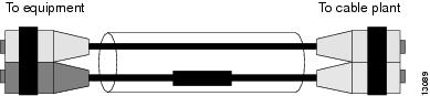
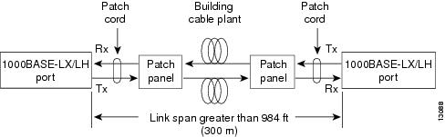
Note  We do not recommend that you use 1000BASE-LX/LH, 10GBASE-LX4 and 10GBASE-LRM transceivers with MMF and no patch cord for very short link distances (tens of meters). The result could be an elevated bit error rate (BER) and receiver damage. We do not recommend that you use 1000BASE-LX/LH, 10GBASE-LX4 and 10GBASE-LRM transceivers with MMF and no patch cord for very short link distances (tens of meters). The result could be an elevated bit error rate (BER) and receiver damage. Figure 2 shows a typical configuration using a patch cord and 1000BASE-LX/LH transceivers. Figure 2 Patch Cord Configuration Patch Cord InstallationThe mode-conditioning patch cord is installed between the transceiver and the patch panel. Two mode-conditioning patch cords are required per installation. To install the patch cord, follow these steps:
Step 1 Plug the single-mode fiber (SMF) connector into the transmit bore of the transceiver. Step 2 Plug the other half of the duplex connector into the receive bore of the transceiver. Step 3 At the other end of the patch cord, plug both MMF connectors into the patch panel. Step 4 Repeat Step 1 through Step 3 for the second transceiver located at the other end of the network link.
|